During this lecture, each group in the class gave initial presentations for their group projects for 'Brief 2', the 'Muesum of Power'.
Our groups chosen theme is to construct an nanimation detailing the history and inner workings of an MK 14E Spitfire.
The group met up during 'Week 3' to discuss the allocation of tasks that each member will contribute to the main project. My allocated task is to create the main airport Hangers and runway.
Friday, 30 October 2009
Thursday, 15 October 2009
Sem.1 Week 4-5: Topology & 3D Mapping of Face
With the face reference plates completed from last week I was then able to go ahead with the Topology of the face from the manipulated photos. While everyone else decided to follow the downloadable tutorial and create their Topologies in Photoshop. I decided to put my artistic talents to good use and do my topology by hand.
I did this for two reasons. Firstly, because I don’t have a very steady hand and so, even when using a graphics tablet, the lines would go all over the place if I used Photoshop, and secondly, I find that it is much easier to draw by hand because I seem to have a knack for being able to copy from a preference picture perfectly as if I had traced it.
So, to this end, I simply printed out the edited photos that I took the previous week, drew the topology lines straight onto the image with a standard HB pencil and, when finished, scanned the complete topology back onto the computer and proceeded with the 3D mapping of the face. (Below is the image of the finished Topology.)
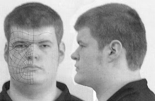
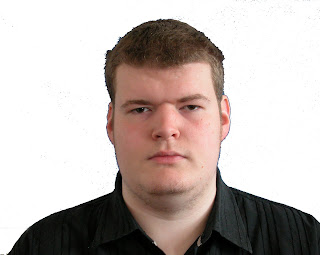
I did come across great difficulties during the Topology to 3D Map stage. The original Topology image was shown heavily pixlelated which proved very difficult to see any of the Topology lines. This was due to having concerns about the overall quality of the original photos. I attempted to remedy this by taking a second set of images during the early hours of the morning at home (photos shown below).
Front View:
Side View:
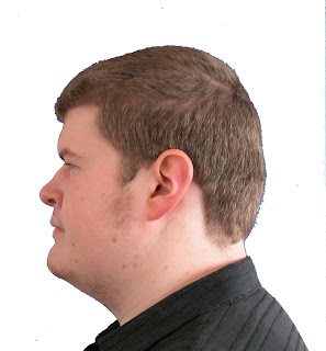
These above images can be seen to be much better quality. However, this was all done before it was brought to my attention that I could in fact adjust the pixel resolution within the ‘3D Studio Max’ Software. This was very good news, because it saved me having to go through the process of creating new face reference plates as well as a new topology and allowing me to continue on with the 3D Map of my Face.
After having sorted out the difficulties with transferring my Topology image to ‘Studio Max’, following the tutorials provided, I set to work on creating the 3D map of the below Topology image.

I started by first creating a normal ‘Plane’ in ‘Studio Max’, changing the number of the ‘Plane’s ‘ segments to ‘Length=1, Width=1’ and adding a material map to the ‘Plane’ of the Topology image (shown below).
Now that the map has been added to the plane I can continue by resizing and adapting the plane to show the whole topology. I did this by going to the ‘Modifier list’ scrolling down to UVW Mapping and then selecting ‘Gizmo’ from the Modifier I added to the plane. This allowed me to position my Topology image so that the Whole face is showing.
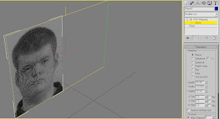
I proceeded from their by right clicking and using the ‘Clone’ tool to copy the plane, rotate to 90 degrees and flip the image to show the side view of the Topology as a guide for the depth of the face.
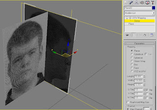
The next stage I did was to build the 2D Grid for, what will eventually be, the 3D map of my face.
I went about doing this by first re-configuring the ‘Views’ in Studio Max to a side by side layout of the front and side ‘Views (shown below).
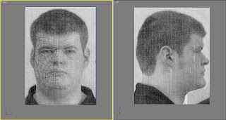
Now that I had these up I began tracing over the Topology lines, by selecting ‘Splines’ and ‘Line tool’. Using the Line tool I began to trace over the Topology lines in four cornered quadrants or ‘Quads’ which I will use to create the 3D map of the Topology later on.
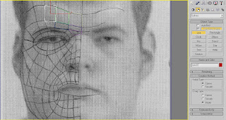
In the above image you can see that some of the quads have traced out already as an example. (It did take a lot of concentration and time to apply this method of tracing each ‘Quad’ of the Topology. It was testing of my patience to say the least, but I did get it done and soke my wrist in cold water afterwards.)
Using these ‘Quads’, once traced around the whole Topology, they can form the basic grid for the 3D Map. I did this by selecting each individual ‘Quad’, right clicking on it and converting it to an ‘Editable Poly’ and began to fill out the lined quads. (An example is shown below.)
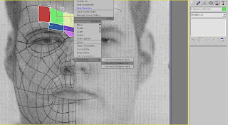
Finally, after converting each ‘Quad’ to ‘Editable Poly’, I got the below, final image.
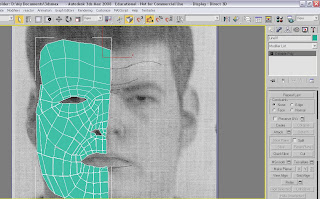
The next step after this would be to join all the quads together so that they all form one surface. However, due to time restriction, this is as far as I am able to get with project.
I do feel that I would have liked to continue more with this assignment but due to difficulties early on I am unable to continue.
I did this for two reasons. Firstly, because I don’t have a very steady hand and so, even when using a graphics tablet, the lines would go all over the place if I used Photoshop, and secondly, I find that it is much easier to draw by hand because I seem to have a knack for being able to copy from a preference picture perfectly as if I had traced it.
So, to this end, I simply printed out the edited photos that I took the previous week, drew the topology lines straight onto the image with a standard HB pencil and, when finished, scanned the complete topology back onto the computer and proceeded with the 3D mapping of the face. (Below is the image of the finished Topology.)

I did come across great difficulties during the Topology to 3D Map stage. The original Topology image was shown heavily pixlelated which proved very difficult to see any of the Topology lines. This was due to having concerns about the overall quality of the original photos. I attempted to remedy this by taking a second set of images during the early hours of the morning at home (photos shown below).
Front View:

Side View:

These above images can be seen to be much better quality. However, this was all done before it was brought to my attention that I could in fact adjust the pixel resolution within the ‘3D Studio Max’ Software. This was very good news, because it saved me having to go through the process of creating new face reference plates as well as a new topology and allowing me to continue on with the 3D Map of my Face.
After having sorted out the difficulties with transferring my Topology image to ‘Studio Max’, following the tutorials provided, I set to work on creating the 3D map of the below Topology image.

I started by first creating a normal ‘Plane’ in ‘Studio Max’, changing the number of the ‘Plane’s ‘ segments to ‘Length=1, Width=1’ and adding a material map to the ‘Plane’ of the Topology image (shown below).

Now that the map has been added to the plane I can continue by resizing and adapting the plane to show the whole topology. I did this by going to the ‘Modifier list’ scrolling down to UVW Mapping and then selecting ‘Gizmo’ from the Modifier I added to the plane. This allowed me to position my Topology image so that the Whole face is showing.

I proceeded from their by right clicking and using the ‘Clone’ tool to copy the plane, rotate to 90 degrees and flip the image to show the side view of the Topology as a guide for the depth of the face.

The next stage I did was to build the 2D Grid for, what will eventually be, the 3D map of my face.
I went about doing this by first re-configuring the ‘Views’ in Studio Max to a side by side layout of the front and side ‘Views (shown below).

Now that I had these up I began tracing over the Topology lines, by selecting ‘Splines’ and ‘Line tool’. Using the Line tool I began to trace over the Topology lines in four cornered quadrants or ‘Quads’ which I will use to create the 3D map of the Topology later on.

In the above image you can see that some of the quads have traced out already as an example. (It did take a lot of concentration and time to apply this method of tracing each ‘Quad’ of the Topology. It was testing of my patience to say the least, but I did get it done and soke my wrist in cold water afterwards.)
Using these ‘Quads’, once traced around the whole Topology, they can form the basic grid for the 3D Map. I did this by selecting each individual ‘Quad’, right clicking on it and converting it to an ‘Editable Poly’ and began to fill out the lined quads. (An example is shown below.)

Finally, after converting each ‘Quad’ to ‘Editable Poly’, I got the below, final image.

The next step after this would be to join all the quads together so that they all form one surface. However, due to time restriction, this is as far as I am able to get with project.
I do feel that I would have liked to continue more with this assignment but due to difficulties early on I am unable to continue.
Friday, 2 October 2009
Sem.1 Week 2-3: Face Reference Plates
To start off with, I opened up Photoshop and opened the two image files of the 2 photos taken of each individual student in the class, uploaded onto memory stick from last week’s lecture.
From there we all proceeded by following the tutorials, provided by the lecturer. By first opening both images on the screen, putting both images in separate layers and then ‘Modifying’ both images so that they both are perfectly symmetrical and the facial features in one photo line up perfectly with the same features in the corresponding photo.
This was done by going to the ‘Filter’ Drop down menu and selecting ‘Distort’. This opens another drop down menu. I then selected ‘Lense Distortion’ and the below box opened.
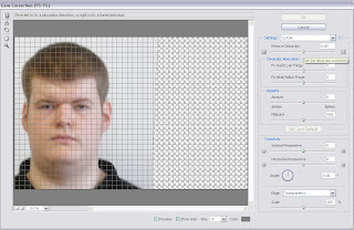
With ‘Lens Distortion’ I was able to correct my two head shots so that the facial features on both lined up exactly. The front view is shown in the above screen dump having already been edited. This is shown as merely an example. You will also notice that the ‘Set distortion correction’ slider is also highlighted with a small text box visible in the top right hand corner.
The end result image of the above edited photo is shown below.
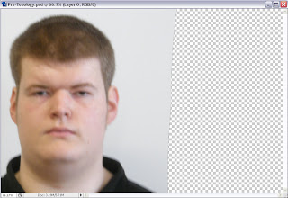
After having done that, I carried on by doing the same for the Side view photo and ended up with the finished image shown below.
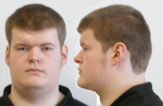
However, to get to the above image I first needed to make sure that the facial features did actually match up correctly. To do this, I selected the ‘Side Layer’ of the image and changed its ‘Opacity’ to 70% in order to accurately position and line up the features of the face to the frontal view.
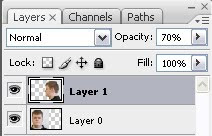
Finally, after having completed this stage I am now able to move onto creating the main Topology.
From there we all proceeded by following the tutorials, provided by the lecturer. By first opening both images on the screen, putting both images in separate layers and then ‘Modifying’ both images so that they both are perfectly symmetrical and the facial features in one photo line up perfectly with the same features in the corresponding photo.
This was done by going to the ‘Filter’ Drop down menu and selecting ‘Distort’. This opens another drop down menu. I then selected ‘Lense Distortion’ and the below box opened.

With ‘Lens Distortion’ I was able to correct my two head shots so that the facial features on both lined up exactly. The front view is shown in the above screen dump having already been edited. This is shown as merely an example. You will also notice that the ‘Set distortion correction’ slider is also highlighted with a small text box visible in the top right hand corner.
The end result image of the above edited photo is shown below.

After having done that, I carried on by doing the same for the Side view photo and ended up with the finished image shown below.

However, to get to the above image I first needed to make sure that the facial features did actually match up correctly. To do this, I selected the ‘Side Layer’ of the image and changed its ‘Opacity’ to 70% in order to accurately position and line up the features of the face to the frontal view.

Finally, after having completed this stage I am now able to move onto creating the main Topology.
Subscribe to:
Comments (Atom)