During this lecture, the group discussed two things.
The first being, the animation of the entire project, there have been concerns that we will not be able to construct the animation we originally planned to implement and instead will be altering the original animation idea. so, instead of having the plane take off, fly around and into a close up to reveal the inner workings of the engine. It will show the plane in flight already, a brief history of the plane and a cut scene of the inner workings of the 'Griffon engine'.
The second thing which was discussed was the script for facts about the Spitfire and its history and a script for a voice over detailing the inner workings of Spitfire Engine.
Friday, 27 November 2009
Tuesday, 24 November 2009
Sem. 1 Week 9-10: Material Maps
I have now begun work on creating the Material Maps for the hangar and adding them to the hangar model.
First, opening Photoshop and opening both the ‘Rivet’ and ‘Stainless Steel’ images. From those images I can create the stainless roof for the Hangar.
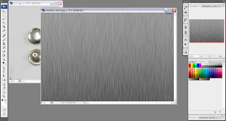
I proceeded from here by increasing the canvas size by four times the current size to create more space to duplicate the stainless steel plates to give a layered effect for the roof.
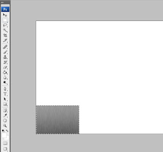
Leaving that for the moment, I set about turning my attention on editing the ‘Rivet’ image by using the ‘Quick Mask Mode’ in Photoshop.
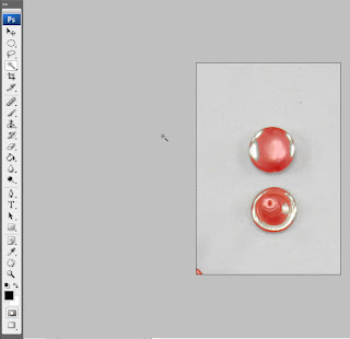
This creates the finished result below.
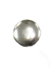
Taking the above image of the ‘Rivet’ I added it onto the ‘Stainless Steel’ image on a separate layer to show a riveted plate. I did this a total of 4 times in each corner.
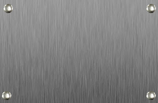
The final step was selecting the riveted, stainless steel image and duplicating it on several layers to fill the remaining canvas space.

Now that the Map has been finished in Photoshop, I can move on to adding both maps to the 3D Model on ‘Studio Max’.
.jpg)
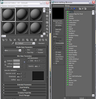
Opening up ‘Hangar example 1.3dsMax scene’ file and opening ‘Material Editor, I selected ‘Diffuse colour’ and selected ‘bitmap’, opening ‘stainless_steel_3.jpg’ and added it to the roof of the hangar model.
After adding the map initially, I found that the image file was much too big because it was showing up as a black on the material editor. I attempted to correct this by changing the size of the image in Photoshop, although it appeared I needed to resize the image several times by tweaking the ‘Image Size’ tool in Photoshop before it would show up on the material editor.
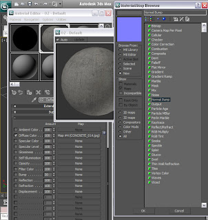
I did the same with ‘CONCRETE_014.jpg’ file and dragged the map from the ‘Material Editor’ to the wall of the hangar.
.jpg)
I showed the progress I made on the model thus far to the lecturer and it was suggested that I add some texture to give the model a bit more depth. I took her suggestion on board and first added a ‘Bump’ Texture to the wall to see how it would look.
.jpg)
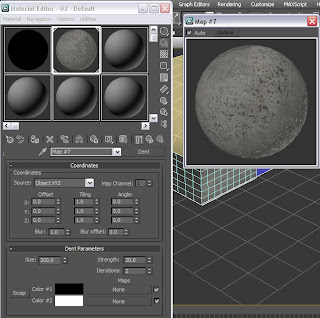
I wasn’t satisfied with the outcome, mainly because it hardly showed at all on the model so I decided to go with a dent texture instead to see if it would give the appropriate effect.
.jpg)
I was pleased with the result as the ‘Dent’ texture did indeed give the concrete wall a more realistic feel.
Now that I am pleased with model textures I decided it was time to group all the model components together so that there would be less to export later.
Before I grouped the hangar components, I decided to first duplicate the hangar by first selecting all the components of the model then, using the ‘Clone’ tool, dragged the copied hangar alongside the first to give a better feel of an airport with multiple aircraft hangars.
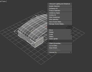
After cloning the hangar I did a render of the scene so far and this is the result.

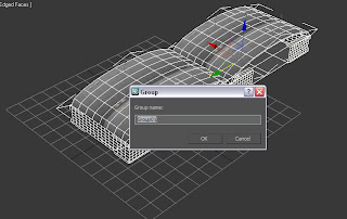
After having rendered the scene and am pleased with the result I clicked on the ‘Group’ icon on the main toolbar in ‘Studio Max’ and named the group ‘Group1’.
First, opening Photoshop and opening both the ‘Rivet’ and ‘Stainless Steel’ images. From those images I can create the stainless roof for the Hangar.

I proceeded from here by increasing the canvas size by four times the current size to create more space to duplicate the stainless steel plates to give a layered effect for the roof.

Leaving that for the moment, I set about turning my attention on editing the ‘Rivet’ image by using the ‘Quick Mask Mode’ in Photoshop.

This creates the finished result below.

Taking the above image of the ‘Rivet’ I added it onto the ‘Stainless Steel’ image on a separate layer to show a riveted plate. I did this a total of 4 times in each corner.

The final step was selecting the riveted, stainless steel image and duplicating it on several layers to fill the remaining canvas space.

Now that the Map has been finished in Photoshop, I can move on to adding both maps to the 3D Model on ‘Studio Max’.
.jpg)
Opening up ‘Hangar example 1.3dsMax scene’ file and opening ‘Material Editor, I selected ‘Diffuse colour’ and selected ‘bitmap’, opening ‘stainless_steel_3.jpg’ and added it to the roof of the hangar model.
After adding the map initially, I found that the image file was much too big because it was showing up as a black on the material editor. I attempted to correct this by changing the size of the image in Photoshop, although it appeared I needed to resize the image several times by tweaking the ‘Image Size’ tool in Photoshop before it would show up on the material editor.
I did the same with ‘CONCRETE_014.jpg’ file and dragged the map from the ‘Material Editor’ to the wall of the hangar.
.jpg)
I showed the progress I made on the model thus far to the lecturer and it was suggested that I add some texture to give the model a bit more depth. I took her suggestion on board and first added a ‘Bump’ Texture to the wall to see how it would look.
.jpg)
I wasn’t satisfied with the outcome, mainly because it hardly showed at all on the model so I decided to go with a dent texture instead to see if it would give the appropriate effect.
.jpg)
I was pleased with the result as the ‘Dent’ texture did indeed give the concrete wall a more realistic feel.
Now that I am pleased with model textures I decided it was time to group all the model components together so that there would be less to export later.
Before I grouped the hangar components, I decided to first duplicate the hangar by first selecting all the components of the model then, using the ‘Clone’ tool, dragged the copied hangar alongside the first to give a better feel of an airport with multiple aircraft hangars.

After cloning the hangar I did a render of the scene so far and this is the result.

After having rendered the scene and am pleased with the result I clicked on the ‘Group’ icon on the main toolbar in ‘Studio Max’ and named the group ‘Group1’.

Friday, 13 November 2009
Sem. 1 Week 8: Start of Designing Animation
This lecture, the rest of the group and I discussed how best to animate the virtual environment, first compiling all of our 3D Modelling pieces and importing them all into one document to then be animated later in the session.
I, regrettably, was unable to contribute my 3D Model of an aircraft hangar due to my 3D Studio Max licence expiring during the previous week. However, I recently applied for and received a new licence with Studio Max software and will be able to proceed with my portion of the modelling.
For this session I began looking for preference images which I will, later, be able to edit to make some material maps to make the 3D Model appear more realistic.
Below are some of the preference pics I will be using:
Stainless Steel:
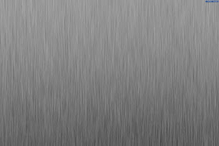
This will possibly be used for the roof and will have a panelled effect. This will include rivets or nails being put on the panels to show how the roof fits together. I will be making these modifications in Photoshop.
Concrete:
(Note: image below is an example.)

It was suggested by the lecturer that the best way to get an idea of what a concrete wall would look like is to actually take a photo of the real thing and then edit it in Photoshop or, in Studio Max, adding a ‘Bump’ texture to it to represent the texture realistically.
Ridged Steel:
I may need to do the same for the ‘Ridged Steel’ as I am going to do with the concrete and take a photo of it and create a material map for it on Photoshop. I intend for this to be used as the upper half for the outside walls of the hangar.
Metal Rivet
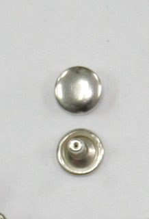
These will be added to the roof material to better show that panels are layered and fastened together to give the illusion of a solid structure.
The above images were found from these Websites:
Steel
Concrete
Metal Rivet
Friday, 6 November 2009
Sem.1 Week 7: Hanger Idea 1 contd.
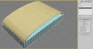
To start off the modelling process of the Hangar, I first opened up a new Studio Max file and created a ‘Tube’ named ‘tube1’, this will become the roof of the hangar(s). The tube dimensions are: H=8 seg, C=1 seg and Sides=18.
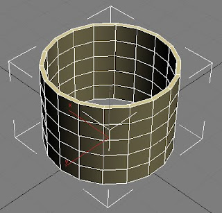
Next, I added an ‘Edit Poly’ modifier to the tube, rotated the tube so that it’s lying on its side with half its mass above and below stage grid and then halved the tube to make a 9 sided semi circular tube. I did this via changing the ‘edit poly’ modifier to ‘Vertex’.
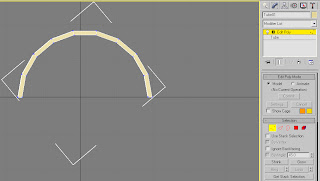
Now that I have the basic shape of the hangar roof I went about reshaping the half tube to better represent the roof in the hangar design shown above. It was suggested to me by my Learning Support Advisor (LSA) that I use the ‘Uniform Scale’ tool, on the main tool bar, to stretch and compress to scale the half tube rather than go use the scenic route and halve the tube again, reshape it one vertex at a time and then duplicate it to get the final result. I personally found the stretch and compress method much easier and less time consuming.
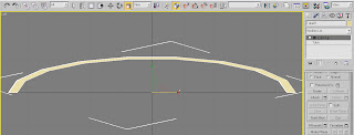
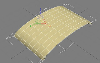
Below is the above image in the perspective view and shows that it has been stretched over all 3 dimensions.
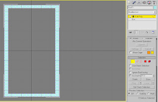
Now that the shape of the roof is done, I moved onto the hangar walls and opening for the doors. I started this by first creating a ‘Box’ called ‘Box1’, and changed the segment dimensions to L=6 seg, W=15 seg and H=33 seg (Shown below).
The step I undertook was hollowing out ‘Box1’ in order to form the walls and doors around the outside. I did this by again adding an ‘Edit Poly’ modifier and changing it to ‘Vertex’ and then deleting the inner segments by selecting all the vertex dots, while in ‘top view’ and clicking delete to leave a 1 segment deep wall around the outside.
After having created the walls the next step was to make a whole for the plane to go through, this will be the hangar door (Shown in the below Screen Dump).
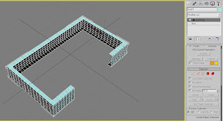
At this stage I discovered a problem with the number of Segments for the height of the box. It appeared that I needed an extra segment on the height of the box for the doors to open and close effectively.
After I tended to this problem, I then started on the doors by creating two planes, rotating them sideways and placing them against the front walls.
Due to new information regarding the animation section which will be done next week, I will not need to create doors for the hanger seeing as the plane won’t be coming out of the hangars.
This said, I can now proceed onto the next step of creating a flat plain for the Hangar floor and begin applying maps and textures to the hangar roof, walls and floor (of which I will begin during next week’s lecture).
Note: Next week the rest of the group will be compiling their 3D models of their allocated tasks and combining them to begin the animation.

Next, I added an ‘Edit Poly’ modifier to the tube, rotated the tube so that it’s lying on its side with half its mass above and below stage grid and then halved the tube to make a 9 sided semi circular tube. I did this via changing the ‘edit poly’ modifier to ‘Vertex’.

Now that I have the basic shape of the hangar roof I went about reshaping the half tube to better represent the roof in the hangar design shown above. It was suggested to me by my Learning Support Advisor (LSA) that I use the ‘Uniform Scale’ tool, on the main tool bar, to stretch and compress to scale the half tube rather than go use the scenic route and halve the tube again, reshape it one vertex at a time and then duplicate it to get the final result. I personally found the stretch and compress method much easier and less time consuming.

Below is the above image in the perspective view and shows that it has been stretched over all 3 dimensions.

Now that the shape of the roof is done, I moved onto the hangar walls and opening for the doors. I started this by first creating a ‘Box’ called ‘Box1’, and changed the segment dimensions to L=6 seg, W=15 seg and H=33 seg (Shown below).

The step I undertook was hollowing out ‘Box1’ in order to form the walls and doors around the outside. I did this by again adding an ‘Edit Poly’ modifier and changing it to ‘Vertex’ and then deleting the inner segments by selecting all the vertex dots, while in ‘top view’ and clicking delete to leave a 1 segment deep wall around the outside.

After having created the walls the next step was to make a whole for the plane to go through, this will be the hangar door (Shown in the below Screen Dump).

At this stage I discovered a problem with the number of Segments for the height of the box. It appeared that I needed an extra segment on the height of the box for the doors to open and close effectively.
After I tended to this problem, I then started on the doors by creating two planes, rotating them sideways and placing them against the front walls.
Due to new information regarding the animation section which will be done next week, I will not need to create doors for the hanger seeing as the plane won’t be coming out of the hangars.
This said, I can now proceed onto the next step of creating a flat plain for the Hangar floor and begin applying maps and textures to the hangar roof, walls and floor (of which I will begin during next week’s lecture).
Note: Next week the rest of the group will be compiling their 3D models of their allocated tasks and combining them to begin the animation.
Thursday, 5 November 2009
Sem.1 Week 7: Hanger Idea 1
I began work on creating a design Idea on how a Spitfire Hanger would have looked like. Below is a design which I am going to be using as a design base for the hangers I plan to implement in Studio Max.
I will want to discuss with the rest of the group next lecture on what Hanger Design I should implement and which would best fit with the period of the airplane the group will be producing.
I will also be printing out a handout, listing the possible hanger design options which I saved from the below website.
www.aircraft-hangars.com
(Note: I also got the above image from the above website.)
Friday, 30 October 2009
Sem.1 Week 6: Project Presentation
During this lecture, each group in the class gave initial presentations for their group projects for 'Brief 2', the 'Muesum of Power'.
Our groups chosen theme is to construct an nanimation detailing the history and inner workings of an MK 14E Spitfire.
The group met up during 'Week 3' to discuss the allocation of tasks that each member will contribute to the main project. My allocated task is to create the main airport Hangers and runway.
Thursday, 15 October 2009
Sem.1 Week 4-5: Topology & 3D Mapping of Face
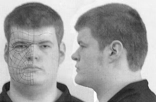
With the face reference plates completed from last week I was then able to go ahead with the Topology of the face from the manipulated photos. While everyone else decided to follow the downloadable tutorial and create their Topologies in Photoshop. I decided to put my artistic talents to good use and do my topology by hand.
I did this for two reasons. Firstly, because I don’t have a very steady hand and so, even when using a graphics tablet, the lines would go all over the place if I used Photoshop, and secondly, I find that it is much easier to draw by hand because I seem to have a knack for being able to copy from a preference picture perfectly as if I had traced it.
So, to this end, I simply printed out the edited photos that I took the previous week, drew the topology lines straight onto the image with a standard HB pencil and, when finished, scanned the complete topology back onto the computer and proceeded with the 3D mapping of the face. (Below is the image of the finished Topology.)
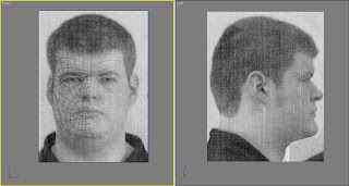
I did come across great difficulties during the Topology to 3D Map stage. The original Topology image was shown heavily pixlelated which proved very difficult to see any of the Topology lines. This was due to having concerns about the overall quality of the original photos. I attempted to remedy this by taking a second set of images during the early hours of the morning at home (photos shown below).
Front View:

Side View:
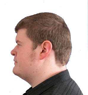
These above images can be seen to be much better quality. However, this was all done before it was brought to my attention that I could in fact adjust the pixel resolution within the ‘3D Studio Max’ Software. This was very good news, because it saved me having to go through the process of creating new face reference plates as well as a new topology and allowing me to continue on with the 3D Map of my Face.
After having sorted out the difficulties with transferring my Topology image to ‘Studio Max’, following the tutorials provided, I set to work on creating the 3D map of the below Topology image.
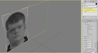
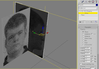
I started by first creating a normal ‘Plane’ in ‘Studio Max’, changing the number of the ‘Plane’s ‘ segments to ‘Length=1, Width=1’ and adding a material map to the ‘Plane’ of the Topology image (shown below).
Now that the map has been added to the plane I can continue by resizing and adapting the plane to show the whole topology. I did this by going to the ‘Modifier list’ scrolling down to UVW Mapping and then selecting ‘Gizmo’ from the Modifier I added to the plane. This allowed me to position my Topology image so that the Whole face is showing.
I proceeded from their by right clicking and using the ‘Clone’ tool to copy the plane, rotate to 90 degrees and flip the image to show the side view of the Topology as a guide for the depth of the face.
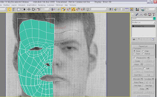
The next stage I did was to build the 2D Grid for, what will eventually be, the 3D map of my face.
I went about doing this by first re-configuring the ‘Views’ in Studio Max to a side by side layout of the front and side ‘Views (shown below).
Now that I had these up I began tracing over the Topology lines, by selecting ‘Splines’ and ‘Line tool’. Using the Line tool I began to trace over the Topology lines in four cornered quadrants or ‘Quads’ which I will use to create the 3D map of the Topology later on.
In the above image you can see that some of the quads have traced out already as an example. (It did take a lot of concentration and time to apply this method of tracing each ‘Quad’ of the Topology. It was testing of my patience to say the least, but I did get it done and soke my wrist in cold water afterwards.)
Using these ‘Quads’, once traced around the whole Topology, they can form the basic grid for the 3D Map. I did this by selecting each individual ‘Quad’, right clicking on it and converting it to an ‘Editable Poly’ and began to fill out the lined quads. (An example is shown below.)
Finally, after converting each ‘Quad’ to ‘Editable Poly’, I got the below, final image.
The next step after this would be to join all the quads together so that they all form one surface. However, due to time restriction, this is as far as I am able to get with project.
I do feel that I would have liked to continue more with this assignment but due to difficulties early on I am unable to continue.
I did this for two reasons. Firstly, because I don’t have a very steady hand and so, even when using a graphics tablet, the lines would go all over the place if I used Photoshop, and secondly, I find that it is much easier to draw by hand because I seem to have a knack for being able to copy from a preference picture perfectly as if I had traced it.
So, to this end, I simply printed out the edited photos that I took the previous week, drew the topology lines straight onto the image with a standard HB pencil and, when finished, scanned the complete topology back onto the computer and proceeded with the 3D mapping of the face. (Below is the image of the finished Topology.)

I did come across great difficulties during the Topology to 3D Map stage. The original Topology image was shown heavily pixlelated which proved very difficult to see any of the Topology lines. This was due to having concerns about the overall quality of the original photos. I attempted to remedy this by taking a second set of images during the early hours of the morning at home (photos shown below).
Front View:

Side View:

These above images can be seen to be much better quality. However, this was all done before it was brought to my attention that I could in fact adjust the pixel resolution within the ‘3D Studio Max’ Software. This was very good news, because it saved me having to go through the process of creating new face reference plates as well as a new topology and allowing me to continue on with the 3D Map of my Face.
After having sorted out the difficulties with transferring my Topology image to ‘Studio Max’, following the tutorials provided, I set to work on creating the 3D map of the below Topology image.
I started by first creating a normal ‘Plane’ in ‘Studio Max’, changing the number of the ‘Plane’s ‘ segments to ‘Length=1, Width=1’ and adding a material map to the ‘Plane’ of the Topology image (shown below).

Now that the map has been added to the plane I can continue by resizing and adapting the plane to show the whole topology. I did this by going to the ‘Modifier list’ scrolling down to UVW Mapping and then selecting ‘Gizmo’ from the Modifier I added to the plane. This allowed me to position my Topology image so that the Whole face is showing.

I proceeded from their by right clicking and using the ‘Clone’ tool to copy the plane, rotate to 90 degrees and flip the image to show the side view of the Topology as a guide for the depth of the face.

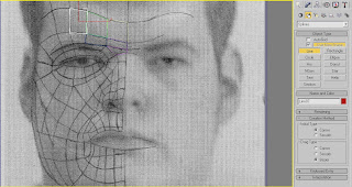
The next stage I did was to build the 2D Grid for, what will eventually be, the 3D map of my face.
I went about doing this by first re-configuring the ‘Views’ in Studio Max to a side by side layout of the front and side ‘Views (shown below).

Now that I had these up I began tracing over the Topology lines, by selecting ‘Splines’ and ‘Line tool’. Using the Line tool I began to trace over the Topology lines in four cornered quadrants or ‘Quads’ which I will use to create the 3D map of the Topology later on.

In the above image you can see that some of the quads have traced out already as an example. (It did take a lot of concentration and time to apply this method of tracing each ‘Quad’ of the Topology. It was testing of my patience to say the least, but I did get it done and soke my wrist in cold water afterwards.)
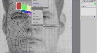
Using these ‘Quads’, once traced around the whole Topology, they can form the basic grid for the 3D Map. I did this by selecting each individual ‘Quad’, right clicking on it and converting it to an ‘Editable Poly’ and began to fill out the lined quads. (An example is shown below.)

Finally, after converting each ‘Quad’ to ‘Editable Poly’, I got the below, final image.

The next step after this would be to join all the quads together so that they all form one surface. However, due to time restriction, this is as far as I am able to get with project.
I do feel that I would have liked to continue more with this assignment but due to difficulties early on I am unable to continue.
Subscribe to:
Comments (Atom)